|
|
默认的后处理,G18,G19平面钻孔还是以Z轴作为进给轴输出XYZ坐标,这样后处理出来的程序无法使用,这次教大家如何正确的输出G18,G19平面的钻孔坐标格式。
这次用到 drl_plane$ 这个变量来判断当前钻孔操作的进给轴 :
返回值 = 0,Z轴 (G17平面)
返回值 = 1,X轴 (G19平面)
返回值 = 2,Y轴 (G18平面)
前提:1. 机床定义添加侧铣头,2. 控制定义中打开 转换NCI坐标至机床试图
其中后处理需要修改2处,1. 不同平面 R 值计算方式的修改,2. 钻孔坐标XYZ的输出格式也需要分别针对G18,G19平面做出更改
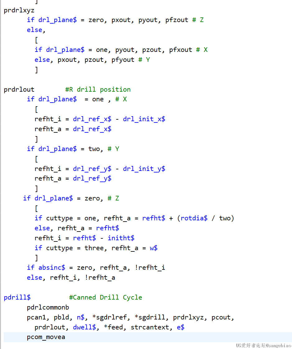
第一步,在后处理中查找 prdrlout 后处理快,利用 drl_plane$ 判断进给轴方向,针对G18,G19平面改变 R 值的计算方式- prdrlout #R drill position
- if drl_plane[ DISCUZ_CODE_3 ]nbsp; = one , # X
- [
- refht_i = drl_ref_x$ - drl_init_x$
- refht_a = drl_ref_x$
- ]
- if drl_plane$ = two, # Y
- [
- refht_i = drl_ref_y$ - drl_init_y$
- refht_a = drl_ref_y$
- ]
- if drl_plane$ = zero, # Z
- [
- if cuttype = one, refht_a = refht$ + (rotdia$ / two)
- else, refht_a = refht$
- refht_i = refht$ - initht$
- if cuttype = three, refht_a = w$
- ]
- if absinc$ = zero, refht_a, !refht_i
- else, refht_i, !refht_a
第二步,同上修改XYZ输出格式
创建后处理块用于输出XYZ坐标
- prdrlxyz
- if drl_plane$ = zero, pxout, pyout, pfzout # Z
- else,
- [
- if drl_plane$ = one, pyout, pzout, pfxout # X
- else, pxout, pzout, pfyout # Y
- ]
第三步,用上一步创建的 prdrlxyz 后处理块替换原有的XYZ输出
- pdrill_2[ DISCUZ_CODE_5 ]nbsp; #Canned Drill Cycle, additional points
- pdrlcommonb
- pcan1, pbld, n$, sgdrlref, prdrlxyz, pcout, prdrlout, feed, strcantext, e$
- pcom_movea

其他钻孔 G83,G73,等只需替换原有的XYZ输出即可
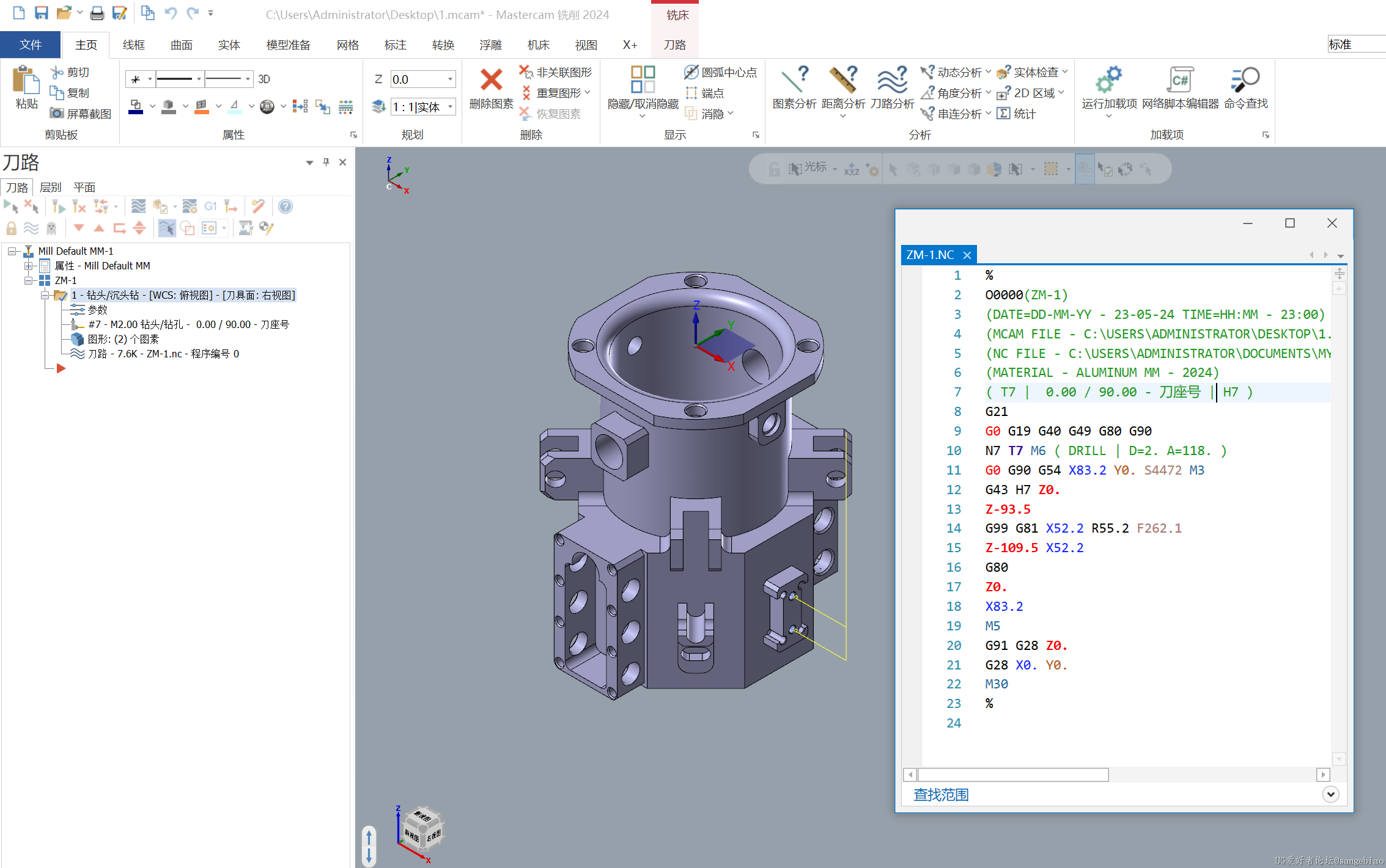
效果:

方法有很多种,以上供大家参考。
|
评分
-
查看全部评分
|